Supermicro X10SRL-F User Manual Page 48
- Page / 129
- Table of contents
- TROUBLESHOOTING
- BOOKMARKS
- X10SRL-F 1
- About This Motherboard 3
- Manual Organization 3
- Contacting Supermicro 5
- Table of Contents 6
- Chapter 3 Troubleshooting 8
- Chapter 4 BIOS 8
- X10SRL-F User’s Manual 10
- •Six (6) SATA cables 15
- •One (1) I/O shield 15
- Motherboard Features 20
- 1-2 Chipset Overview 23
- 1-3 Special Features 24
- 1-4 PC Health Monitoring 24
- 1-5 ACPI Features 25
- 1-6 Power Supply 25
- Chapter 2 27
- Installation 27
- Product Disposal 29
- Precautions 30
- Unpacking 30
- Location of Mounting Holes 31
- Tools Needed 31
- Installing the Motherboard 32
- WARNING! 33
- OPEN 1st 36
- Removing the Heatsink 38
- 2-5 Installing DDR4 Memory 39
- Removing Memory Modules 40
- Memory Support 40
- Memory Population Guidelines 40
- 2-6 Connectors/IO Ports 43
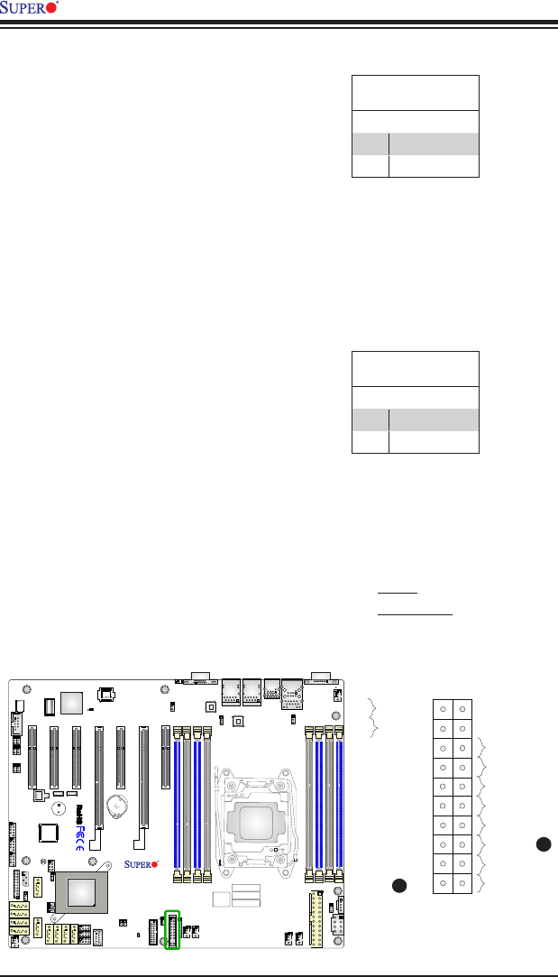
- Front Control Panel 47
- 2-7 Connecting Cables 52
- Standby Power 55
- A. TPM/Port 80 57
- B. VGA Port 57
- 2-8 Jumper Settings 58
- A. Watch Dog Enable 61
- B. BIOS Recovery 61
- 2-9 Onboard Indicators 63
- Blinking 64
- BMC: Normal 64
- 2-10 SATA Connections 65
- Chapter 3 67
- Troubleshooting 67
- No Video 68
- Memory Errors 68
- •System conguration 69
- Battery Removal 71
- Proper Battery Disposal 71
- Battery Installation 71
- Chapter 4 73
- 4-2 Main Setup 74
- Boot Feature 76
- Power Conguration 77
- CPU Conguration 78
- CPU P State Control 80
- CPU C State Control 81
- CPU T State Control 81
- Chipset Conguration 82
- North Bridge 82
- IIO Conguration 82
- IIO1 Conguration 82
- IOAT Conguration 82
- •Number of CPU 83
- •Number of IIO 83
- Memory Conguration 84
- DIMM Information 85
- Conguration 85
- •USB Conguration 87
- •USB Module Version 87
- •USB Devices 87
- •Software Preserve Support 88
- PCIe/PCI/PnP Conguration 92
- Super IO Conguration 94
- ACPI Settings 100
- 4-4 Event Logs 101
- View System Event Log 102
- 4-5 IPMI 103
- BMC Network Conguration 104
- Chapter 4: AMI BIOS 105
- Gateway IP Address 105
- 4-6 Security 106
- 4-7 Boot 107
- 4-8 Save & Exit 109
- Appendix A 111
- BIOS Error Beep Codes 111
- Appendix B 113
- B-2 Installing SuperDoctor5 114
- Appendix C 115
- Appendix D 119
- D-1 IPMI GUI Browser 120
- Appendix D: Dual Boot Block 121
- D-2 IPMI Command Sets 125
- User Approach 127
Related products and manuals for Server/workstation motherboards Supermicro X10SRL-F
 (109 pages)
© 2020, manymanuals.com. All rights reserved. | 0.694 s |
 Manymanuals.com
 Manymanuals.de
 Manymanuals.fr
 Manymanuals.it
 Manymanuals.pl
 Manymanuals.cz
 Manymanuals.es
 Manymanuals-pt.com
Comments to this Manuals